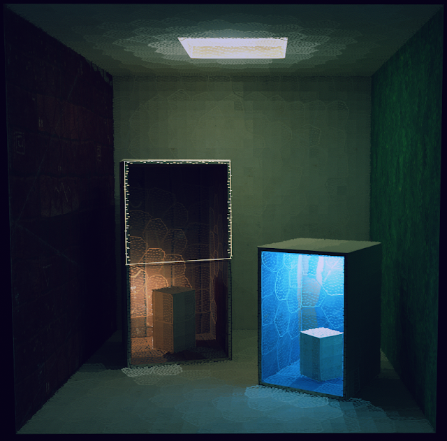
In keeping with a lot of the older posts on this blog I thought I'd write about the realtime GI system I'm using in a project I'm working on. It's a complete fresh start from the GI stuff I've written about previously. Previous efforts were based on volume textures but dealing with the sampling issues is a pain in the ass so I've switched to good old fashioned lightmaps. This is all a lot of effort to go to so why bother? The short answer is I love the way it looks. As a bonus it simplifies the lighting process and there's a subtlety to the end results that is very hard to achieve without some sort of physically based light transport. A single light can illuminate an entire scene and the bounce light helps ground and bind all the elements together.
The process can be divided into five stages, lightmap UVs, surfel creation, surfel clustering, visibility sampling and realtime update.The clustering method was inspired by this JCGT article however I'm not using spherical harmonics and I generate surfels and form factor weights differently. The JCGT article is fantastic and well worth a read.
Before you run off, here it is in action.
Lightmap UVs
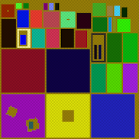
 The lighting result is stored in a lightmap so the first step is a good set of UVs. These lightmaps are small and every pixel counts so you have to be pretty fussy about how the UVs are laid out. UV verts are snapped to pixel centers and there needs to be at least one pixel between all charts in order to prevent bilinear sampling from sampling incorrect charts. The meshes are unwrapped in Blender then packed via a custom command line tool. This uses a brute force method that simply tests each potential chart position in turn, for simple scenes and pack regions up to 256x256 the performance is acceptable.
Surfels and Clustering
Next up we have to divide the scene into surfels (surface elements) and then cluster those surfels into a hierarchy. At runtime these surfels are lit and the lighting results are propagated up the hierarchy. This lighting information is then used to update the lightmap.Surfel placement plays a big part in the quality of the illumination and I've been through a few iterations. Initially I tried random placement with rejection if a surfel was too close to it's neighbours but this was hellishly slow. I also tried a 3D version of this which was much faster but looking at the results I felt the coverage could be better. Particularly around edges and on thin objects, the neighbour rejection techniques would often leave gaps that I felt could be filled. This seemed like it could be addressed by relaxing the points but I wanted to try something else.
I decided to try working in 2D using the UV's which in this case are stretch free, uniformly scaled and much easier to work with. The technique I settled on first generates a high density, evenly distributed set of points on each UV chart. N points are selected from this set and used as initial surfel locations and these locations are then refined via k-means clustering.
This results in a set of well spaced surfels that accurately approximate the scene geometry and makes it easy to specify the desired number of surfels. For each chart N is simply
(chart_area / total_area) * total_surfel_count
 | |
| The initial high density point distribution. |
 |
| Surfel creation via k-means clustering of the high density point distribution. |
These surfels are then clustered via hierarchical agglomerative clustering which repeatedly pairs nearby surfels until the entire surfel set is contained in a binary tree. Distance, normal, UV chart and tree balancing metrics help tune how the hierarchy is constructed. I'm still experimenting with these factors.
 |
| Hierarchical agglomerative clustering in action. |
Lightmap visibility sampling
 |
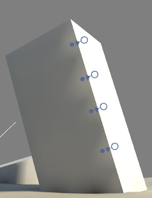
| Influencing clusters for the highlighted lightmap texel. |
num_hits / total_rays
Once all rays have been cast the form factor weights are propagated up the hierarchy. The hierarchy is then refined by successively selecting the children of the highest weighted cluster. At each iteration the highest weighted cluster is removed and it's two children are selected in it's place. This process repeats until a maximum number of clusters is selected or no further subdivision can take place. The texel then has a set of clusters and weights that best approximate it's lighting environment.
Lighting update
The realtime lighting phase consists of several stages. First the surfels direct lighting is evaluated for each direct light source, visibility is accounted for by tracing a single ray from the surfels position to the light source. The lighting result from the previous frame is also added to the current frames direct lighting to simulate multiple bounces. There's a bit of a lag here but it's barely noticeable. Lighting values for each cluster are then updated by summing the lighting of it's two children.Each active texel in the lightmap is then updated by accumulating the lighting from it's set of influencing clusters. The lightmap is then ready to be used.
 |
| Direct light only. |
 | |
| Direct light with one light bounce. |
 |
| Direct light with multiple light bounces. |
Timings for each stage (i7-6700k @ 4.0ghz)
Surfel illumination (1008 surfels): 0.36ms
Sum Clusters (2015 clusters): 0.08ms
Sum Lightmap texels (6453 texels * 90 clusters): 0.64ms
Environmental Lighting
To finish up here are some more examples without any debug overlay. These were taken with an accumulation technique that allows for soft shadows and nice anti-aliasing.


